Hoppe Profile Cylinder Install Instructions
Tools Required:
Phillips Head Screw Driver
Hex Wrench (provided)
Ring Wrench (provided)
Pliers
A Guide to Install Hoppe Key Cylinder and Half Cylinders:
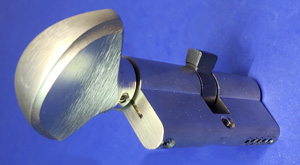
- Loosen set screw (C) on knob (D) using the hex wrench provided. Knob designs may vary from design shown.
- Remove knob (D) from body of cylinder (B).
- Align drive tab (J) with the cylinder body to install the cylinder into the lock as shown by (G). If the drive tab (J) cannot be rotated to this position, push the pin (E) down with the ring wrench (F) to disengage the stops and turn the cylinder shaft (B) until the drive tab (J) is aligned with the cylinder as shown by (G).
- Holding in this position, insert the cylinder body into the lock so the drive tab (J) is inside of the lock.
- Rotate the shaft (B) (use pliers if necessary) such that the top of the shaft (B) moves toward the edge of the door or insert the key (A) into the cylinder and rotate such that the top of the key (A) moves towards the edge of the door (H). The shaft or key will rotate freely and will stop after approximately 120°. Do not force rotation. The dead bolt should not extend (dead bolt will extend on single point gear). Confirm that one of the two set screw openings is positioned on the bottom of the shaft (B).
Warning: If the shaft (B) or key (A) is rotated the wrong direction, the cylinder will lock after approximately 120° and cannot be rotated in either direction. If this happens, push the pin (E) down with the ring wrench (F) included to disengage the stops and turn the shaft (b) or key (A) in the opposite direction until the dead bolt extends.
- Fix knob (D) on shaft (B) as shown.
- Tighten set screw (C). Install cylinder screw (K) as shown.
Removal:
1. Loosen and remove cylinder screw (K) and repeat steps 1-4 above.

Categories
Manufacturers
- 0 items