Installation Of Hoppe Multipoint Door Locks
This is for Active Hoppe multipoint door locks and In-Active Hoppe door locks.
**Main gear and extensions should be hand-tightened only. Excessive force may cause drive rail to bind and cause operational problems.
- Position the lockcase as if you were about to insert it into the door. Make sure the latch bevel and mishandling latch are facing the right direction. It should be facing in a direction that when the door closes, the bevel allows the door to clear the edge of the door frame and the latch is able to slide into the strike plate in the doorframe. If the bevel is facing the wrong direction, the door will not be able to clear the edge of the frame at all.
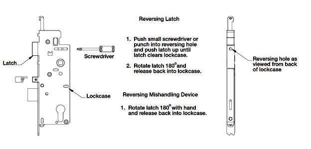
-Note: If you need to reverse the latch, push a small screwdriver or punch into reversing hole and push latch up until latch clears lockcase. Rotate latch 180° and release back into lockcase. (See below)
- Insert the main gear (gearbox and lower extension) into the mortised space in the door, aligning the holes drilled in door face with the profile cylinder, handle holes and lockcase to properly accommodate trim.
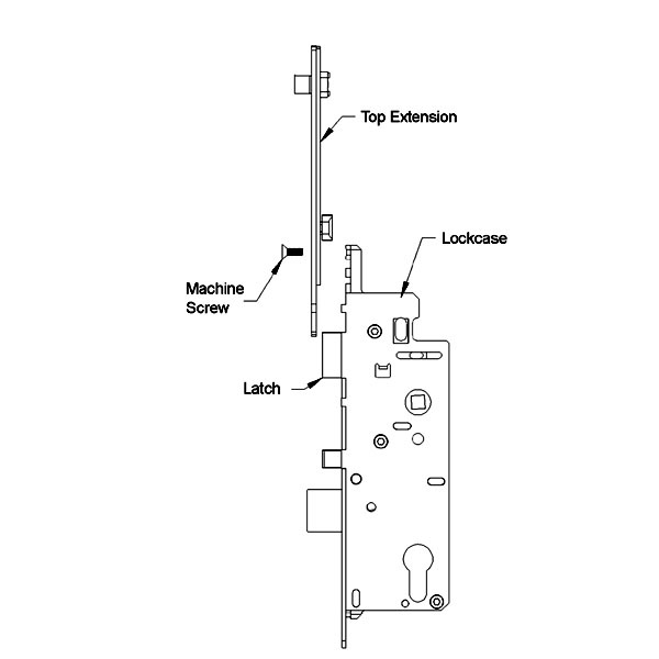
- Remove the machine screw in top of the lockcase. Insert top extension into place and then reinsert the machine screw back into place securely. Then reinstall the Phillips screws in the faceplate along the edge of the door. The screws should be installed flush with the faceplate, but not over-tightened.
Be sure to connect the “T” connector on the back of the faceplate of the top or middle extension to the main gear.
If you purchased a new Hoppe tongue, roller, roundbolt or swinghook top extension, you may need to trim the excess off the top of the new top extension faceplate to fit your door size.
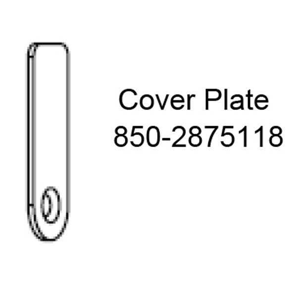
- If you have a Hoppe shootbolt multipoint lock, you will also need to connect the top shootbolt extension and the cover plate 850-2875118. If you are reusing an existing Hoppe top shootbolt extension, you just need to reconnect the drive rail serrations from the top shootbolt extension into the middle extension coupler. See #3B below for proper connecting instructions. Then reinstall the installation screws and cover plate securely.
If you purchased a new Hoppe top shootbolt extension, you may need to trim your extension to your door size. You will need a hacksaw to trim the top shootbolt extension.
If replacing an already existing lock, once you've removed the old lock, use it to measure the new one. Place them next to each other and double-check with a tape measure to ensure that you know what length you need to cut your lock.
YOU MUST EXTEND THE SHOOTBOLT BEFORE TRIMMING. Extend the shootbolt so it is in the locked position before you trim. This ensures that you trim off the same amount of faceplate and teeth serration. You can use a clamp or vice grip to keep the serrated teeth in place with the faceplate while trimming.
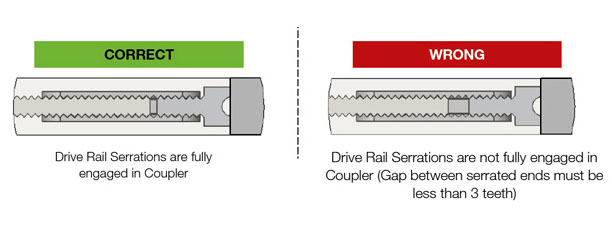
**Make sure you leave at least 1-3/4” of teeth serration on the drive rail remaining to drop down into the middle extension coupler. This is the section that connects the top extension to the middle extension. Exact measurements may differ depending on your door height. - After installing the Active Gear/Bottom Extension, the Middle Extension, and cutting the Top Shootbolt Extension to length:
Insert the drive rail serrations into the coupler as shown below and slide the top extension faceplate flush against the middle extension faceplate. The top shootbolt should now be fully retracted into the shootbolt housing.
Then install the cover plate to reinforce the connection between the Middle Extension and Top Shootbolt Extension and then install remaining screws to secure the top shootbolt extension to the door.
- If you have a Hoppe shootbolt multipoint lock, you will also need to connect the top shootbolt extension and the cover plate 850-2875118. If you are reusing an existing Hoppe top shootbolt extension, you just need to reconnect the drive rail serrations from the top shootbolt extension into the middle extension coupler. See #3B below for proper connecting instructions. Then reinstall the installation screws and cover plate securely.
- Reinstall the handle set for your door using the instructions for your handle.
- Inspect for Proper Installation and Test Functionality of the door lock in the OPEN Position:
With the door in the open position, press in the mishandling device then engage the locking system by lifting the handle and extend the deadbolt by turning the thumbturn. The multipoints and deadbolt should now be extended in the locked position, if that is the case, your lock is fully operational
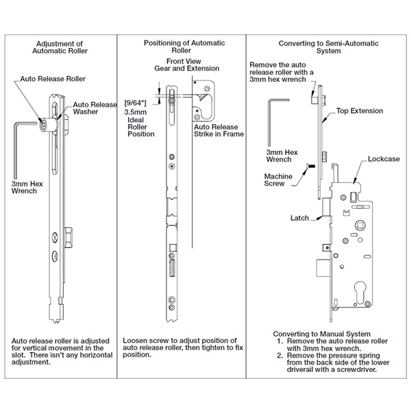
Hoppe HLS9000 Hardware Adjustments:
Hoppe Inactive Shootbolt Lock Assembly Instructions
We recommend assembly of the inactive gear in the activated (locked) position. To be consistent in the operation and assembly, you should assemble the gear operator as follows:
Install main gear body assembly into stile:
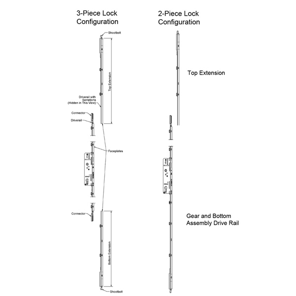
- Align the main gear body within the mortise. If you're using a jig to center the gear on the handle hole, slide the gear body into place and screw it down. If you're not using a jig, align the gear with the panel bottom. If your lock is a 3-piece, extend the shootbolts of the bottom extension and set the extension in place along the door. Line up the main gear body with the bottom extension and mark your installation point from there. Screw in place.
- Operate and extend the shootbolt mechanism with the handle. Then lock the thumb-turn mechanism (cylinder). The thumb-turn mechanism will spin freely after it hits the locking point. If the thumbturn mechanism feels as though it has hit the locking point but does not spin freely, the mechanism is not working properly.
- If your lock is a 3-piece, connect the drive rail of the bottom extension to the connector of the main gear. Make sure the teeth are fully engaged and seated in the connector. The shootbolts should extend ¾” or 1” (model options). Screw the bottom extension to the stile.
- Connect the drive rail of the top extension to the connector of the main gear. Make sure the teeth are fully engaged with the main lock and then install the screws to the top extension into the stile. The shootbolts should extend 3/4" or 1".
Note: Tolerance – There is an allowance of up to 1/8” (3mm) between the gear and extensions. - Finish screwing the inactive system onto the stile. Be sure you install screws in the holes that will not be filled when the astragal is applied.
- Unlock the thumbturn mechanism. Operate the handle to retract and extend the shootbolts. The shootbolt mechanisms should operate freely.
- Now try to operate the shootbolts while the lock is engaged. The shootbolts should not retract.
Categories
Manufacturers
- 0 items